Compressor package configuration
Industrial Refrigeration Compressor Packages
Select an industrial compressor package from the refrigerant, required refrigeration duty, operating temperatures, electrical supply and expected load variation. For an existing plant, drawings and operating records help identify replacement and integration requirements.
- System role
- Pressure and capacity control
- Key inputs
- Duty, conditions and power
- Project fit
- Layout, controls and access
01
Compressor Package Configuration
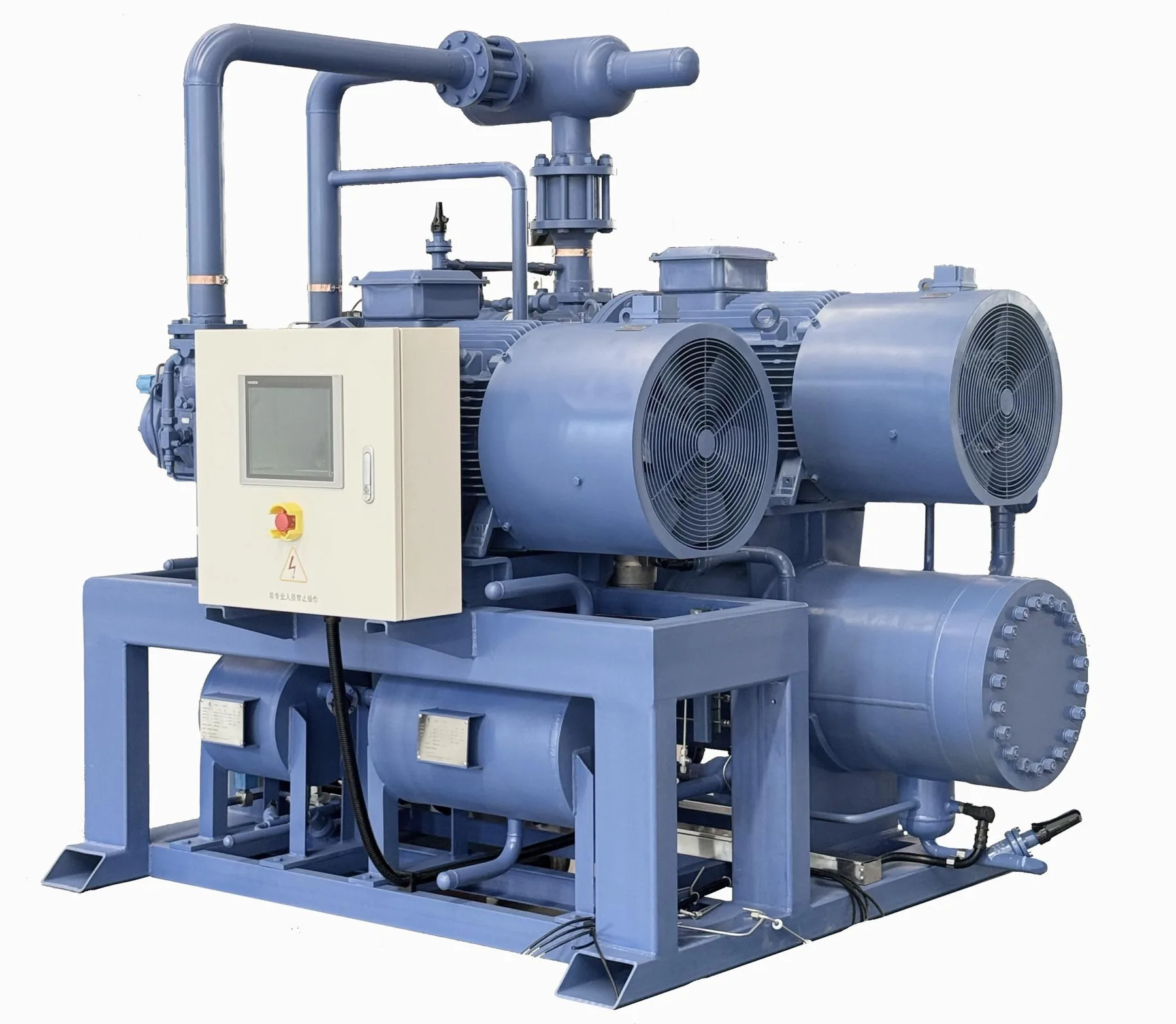
A compressor package manages the pressure difference that moves heat through an industrial refrigeration system. It is connected to the selected refrigerant arrangement, heat rejection, liquid management, room or process terminals, controls, power supply and piping. The package should therefore be reviewed as part of the complete system duty rather than selected as a stand-alone online product.
The required duty is shaped by room operation, product movement, process load, ambient conditions, operating hours and the selected system conditions. A storage facility may have different peak requirements from a processing line, a freezer or a multi-temperature warehouse. Documenting those conditions gives the configuration review a clear basis.
02
Select the compression arrangement through operating conditions
Open and semi-hermetic compressor arrangements, parallel packages, single-stage or multi-stage concepts, and associated auxiliaries can each be considered where they are suitable for the duty and available configuration scope. The appropriate route depends on refrigerant strategy, suction and discharge conditions, capacity range, part-load operation, service approach, local codes and the system architecture.
The purpose of a parallel package is not simply to add more compressors. Staging and capacity control should follow the load profile and the expected operating pattern. A project team should identify product peaks, room recovery periods, process schedules and expected minimum operating load so that control logic can be reviewed with the machinery arrangement.
03
Capacity control, controls and auxiliary interfaces
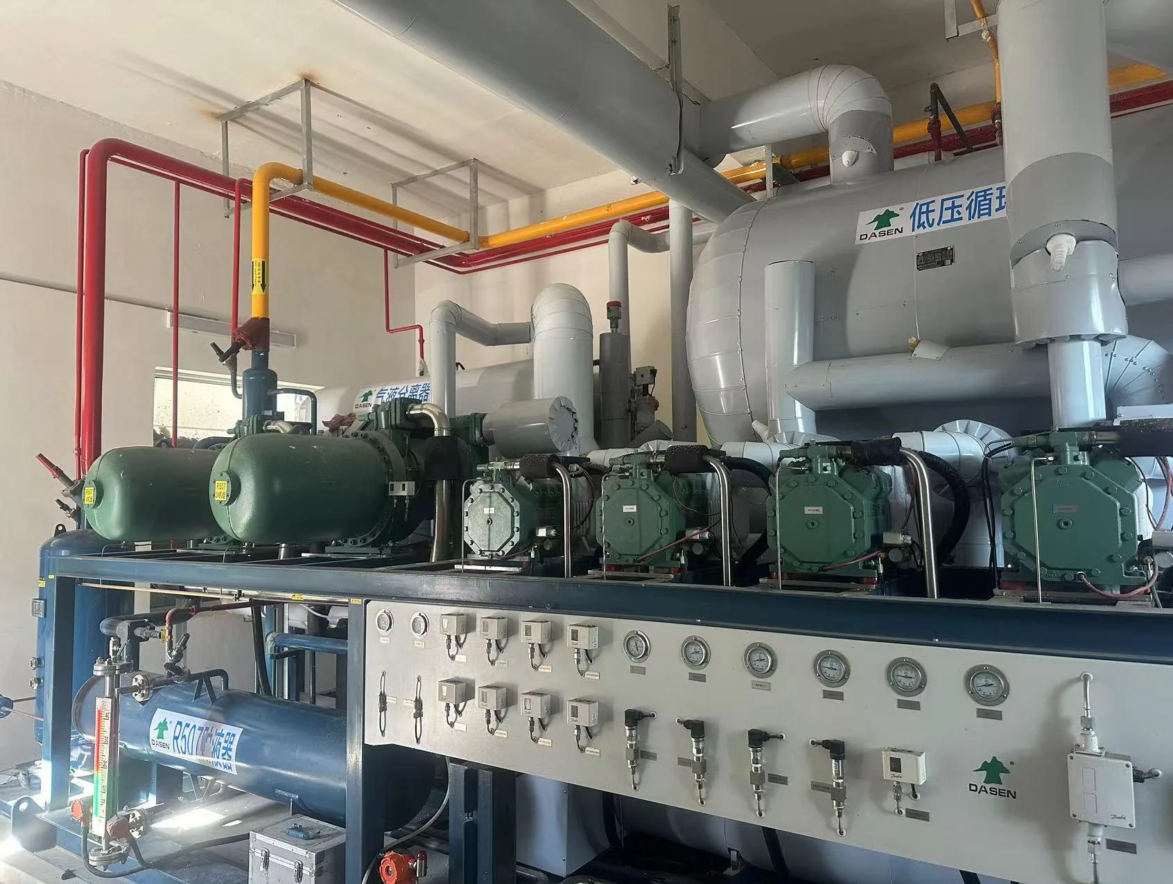
Capacity control is connected to the system’s pressure, temperature and operating signals. Controls may coordinate compressor stages, safety functions, alarms, heat-rejection response, defrosting interactions and the way the operating team receives information. The actual point list, alarm strategy, network access and user roles should be written into the project brief rather than assumed from a panel photograph.
Oil management and other auxiliary components may be relevant depending on the selected refrigerant, compressor arrangement and system design. Their inclusion, connection, maintenance approach and instrumentation need to follow the reviewed configuration. A detail page can explain the questions; it cannot replace a current approved selection sheet or project-specific engineering.

04
Installation and Maintenance Access
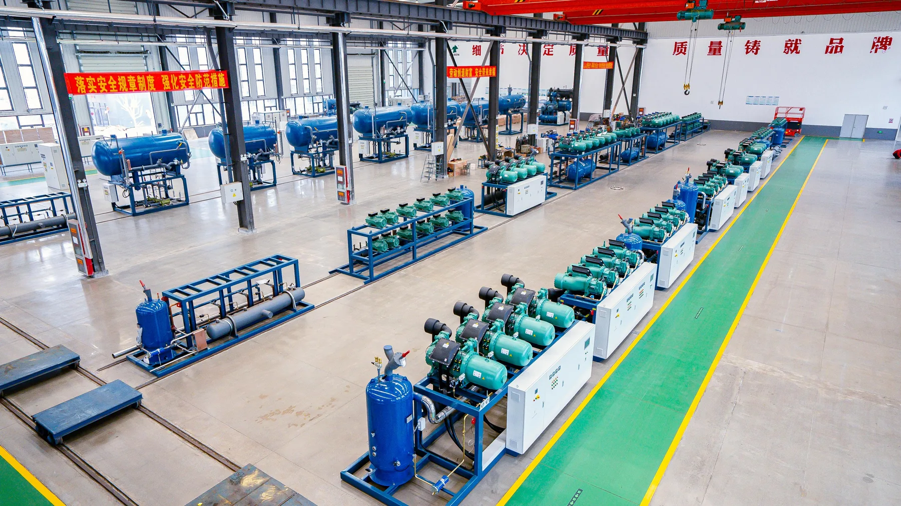
A compressor package needs a practical location, service clearance and safe route for installation and future maintenance. Plant-room dimensions, door widths, lifting path, foundation or support conditions, ventilation, electrical isolation, drainage, noise constraints and pipework access should be reviewed before the unit is treated as installable.
For replacement work, the survey should also record existing electrical supply, controls, pipe sizes, valve stations, operating records, temporary capacity needs and shutdown windows. This information supports a staged plan that protects product while allowing the old and new equipment interfaces to be managed responsibly.
05
Prepare a useful request for configuration review
A useful RFQ identifies the application, refrigerant strategy if known, required duty or load inputs, room and process conditions, target operating temperatures, heat-rejection conditions, power supply, project country, schedule, plant-room layout and the expected delivery boundary. For a retrofit, include available photos, drawings, equipment records and the required operating continuity.
The next step is not a generic performance promise. It is a documented review of the available conditions, the equipment configuration, accessories, controls, delivery interface and the conditions that remain to define in the scope. The Project Brief Builder accepts the available facts and lets a team mark technical details as unknown where assistance is required.
06
Coordinate the package with heat rejection and room demand
The compressor package does not establish system performance on its own. Its response is affected by the heat-rejection side, the room or process terminals, the defrosting approach, liquid management, pipework and the control strategy. A change to condenser conditions, a new room, a different product schedule or an altered defrosting pattern can change the way the package needs to operate.
For that reason, the RFQ should show what else is connected to the machinery. Identify the number and purpose of rooms, process equipment, expected product movement, operating shifts, heat-rejection conditions and any future expansion assumptions. This does not turn a web page into a design; it gives a configuration review the context needed to avoid isolated-equipment decisions.
07
Plan records, commissioning and handover
Before commissioning, the responsible parties should agree what mechanical, electrical, control, safety and documentation conditions must be complete. Depending on the scope, this can include equipment identification, electrical protection, piping and valve checks, control-point verification, alarm testing, drainage, access, operating instructions and the handover record. The relevant specialists determine the actual testing and compliance requirements for the project.
After start-up, the operating team benefits from a clear record of the installed configuration, key operating settings, alarm contacts, maintenance access and the boundaries between equipment supply, local installation and ongoing support. These records make future troubleshooting and planned maintenance more practical, particularly where a plant will be expanded or modernized in stages.
08
Compare package arrangements against the duty
Open and semi-hermetic compressor arrangements can be considered with the refrigerant strategy, access for service, available support and the selected system conditions. Single-compressor packages can suit one defined duty, while parallel packages can stage compressors as demand changes. Single-stage or two-stage arrangements depend on the temperature range, system design and operating conditions.
The useful comparison is not a catalogue ranking. It is whether the arrangement can cover the stated load profile, minimum operating demand, heat-rejection conditions, controls needs and maintenance plan. State what is known and mark the remaining inputs for follow-up rather than assuming a capacity or compressor type.
09
Give the package a complete selection record
A procurement request should show the refrigerant if selected, suction and discharge or evaporating and condensing conditions, duty or calculation inputs, part-load pattern, power supply, heat-rejection arrangement, controls requirements, plant-room layout and required accessories. Include available equipment lists, photos, piping drawings and control records for a replacement project.
The proposed supply can then identify items such as controls, valves, vessels, oil-management components where applicable, instruments, electrical requirements and connection points. The quotation should distinguish these from local pipework, power connection, lifting, ventilation, drainage and installation work.
| Arrangement | When it may be considered | Configuration focus | Information needed before quotation |
|---|---|---|---|
| Open compressor package | Projects with a compatible refrigerant strategy and service plan | Drive, service access, auxiliaries and plant-room layout | Refrigerant, duty, operating conditions, access and maintenance approach |
| Semi-hermetic package | Projects where the operating envelope and available configuration support it | Staging, controls, service access and power | Duty, temperature conditions, load profile and electrical data |
| Single-compressor package | A defined load with an appropriate operating profile | Duty range, standby strategy and controls | Load variation, recovery periods and continuity requirement |
| Parallel package | Projects with changing load across rooms or process periods | Compressor staging, part-load response and controls | Minimum/peak demand, room schedule, expansion and control intent |
| Single or two-stage concept | Systems where the selected temperature range and architecture require comparison | Operating conditions, refrigerant route and auxiliaries | Evaporating/condensing conditions, product duty and system layout |
| Selection field | Example record | Why it is used |
|---|---|---|
| Application | Cold storage, process cooling, freezing or retrofit | Connects the package to room and product duty |
| Refrigeration conditions | Refrigerant, target temperatures and heat-rejection conditions | Sets the expected operating envelope |
| Duty and load variation | Calculation inputs, daily intake, shift pattern and peak periods | Supports capacity control and compressor staging |
| Power and controls | Voltage, frequency, protection, points, alarms and integration need | Defines electrical and control interfaces |
| Plant-room information | Layout, doors, lifting route, ventilation, drainage and clearances | Confirms delivery, installation and maintenance access |
Questions to discuss
Frequently asked questions
What should be supplied for an initial compressor package review?
Provide the application, refrigerant approach if known, load or operating inputs, system conditions, heat-rejection context, power supply, plant-room layout, project country and required delivery scope. Existing records and photos are useful for retrofit work.
Can a web image establish a final equipment selection?
No. Images explain equipment context. A current configuration needs the actual operating conditions, approved technical data and a defined project boundary.
Why does plant-room access appear in an equipment review?
Service clearance, lifting, power, ventilation, drainage, pipework and controls access affect whether equipment can be installed and maintained safely in the available space.
A clear next step
Tell us what you need to store, cool or freeze.
Use the Project Brief Builder to capture the available product, condition, room, throughput and scope information.